Valve list
| Item | Type | Size |
|---|---|---|
| V01 | Diaphragm valve | 60-CL600 |
| V02 | Flanged ball valve | 48-CL600 |
| V04 | Flanged pressure safety valve | 60-CL900 x 89-CL300 |
| V08 | Threaded ball valve | 60-CL600 |
| V10 | Threaded gate valve | 60-CL600 |
+ 10 more rows
Obsidian Engineering · AI team
A flat PDF. No layers, nothing to edit, nothing software can read. Follow one back into engineering data, and see everything that comes from it.
1 PDF to CAD Demonstrated
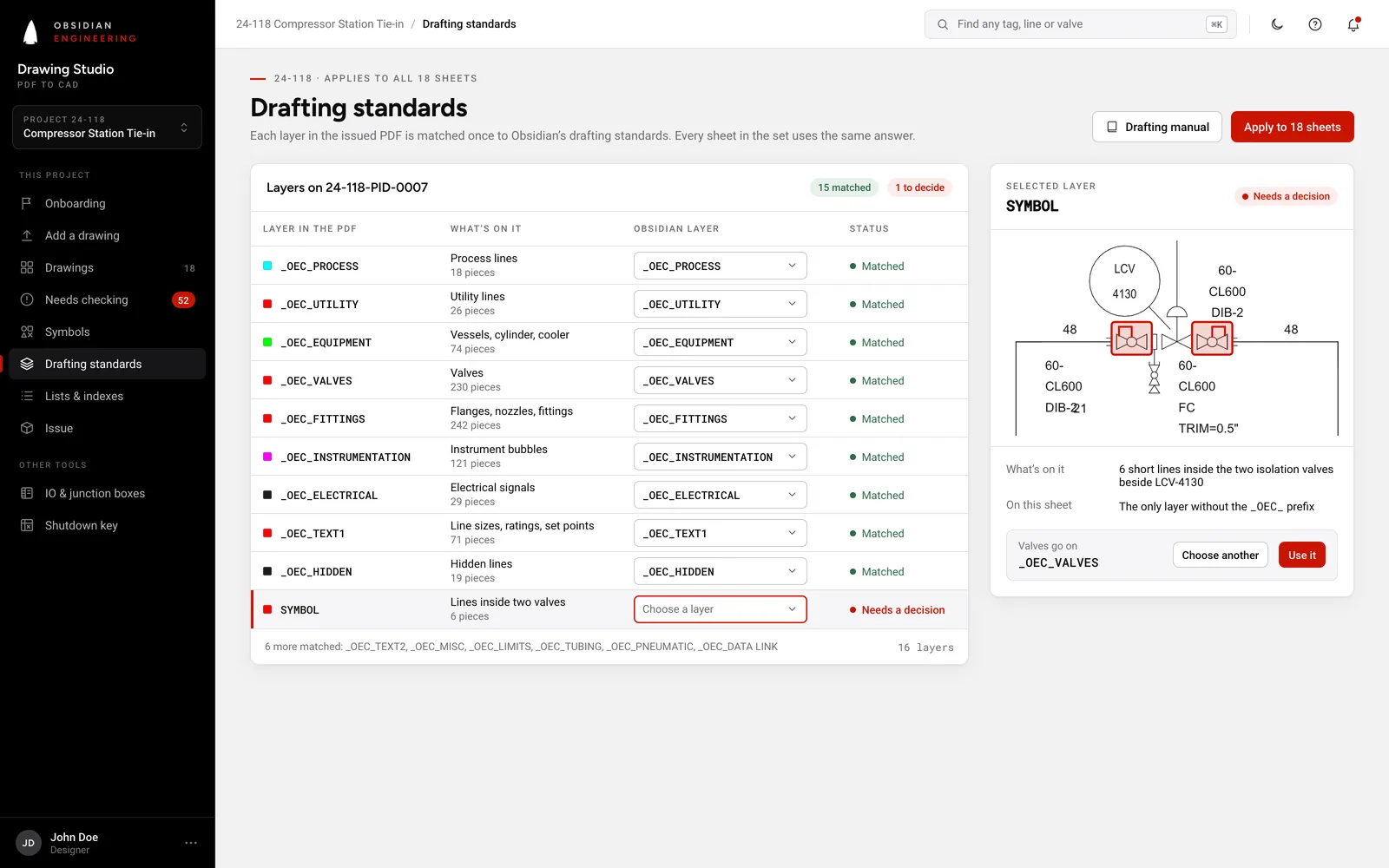
15 layers on Obsidian's own drafting standard, each in the colour the manual gives it.
The same sheet, layered, the way it opens in AutoCAD. Everything below is read from it.
_OEC_BORDER_OEC_LIMITS_OEC_PROCESS_OEC_UTILITY_OEC_EQUIPMENT_OEC_VALVES_OEC_FITTINGS_OEC_INSTRUMENTATION_OEC_MISC_OEC_TUBING_OEC_PNEUMATIC_OEC_DATA LINK_OEC_ELECTRICAL_OEC_TEXT1_OEC_TEXT2Obsidian Drawing Studio In development
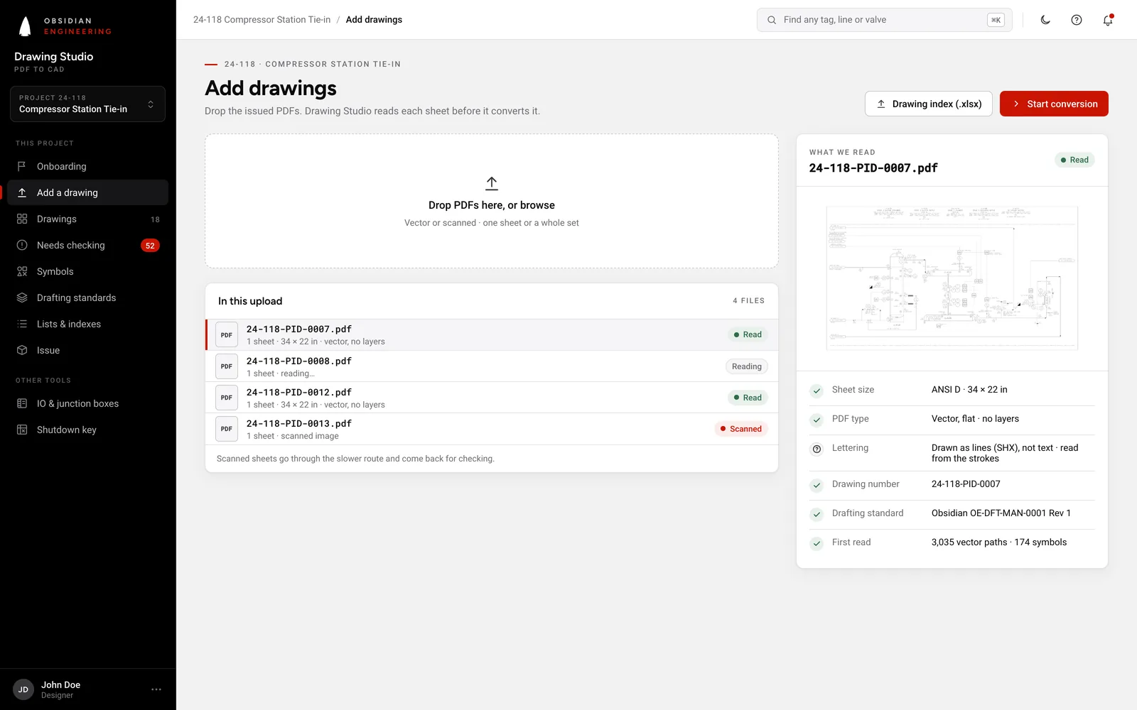
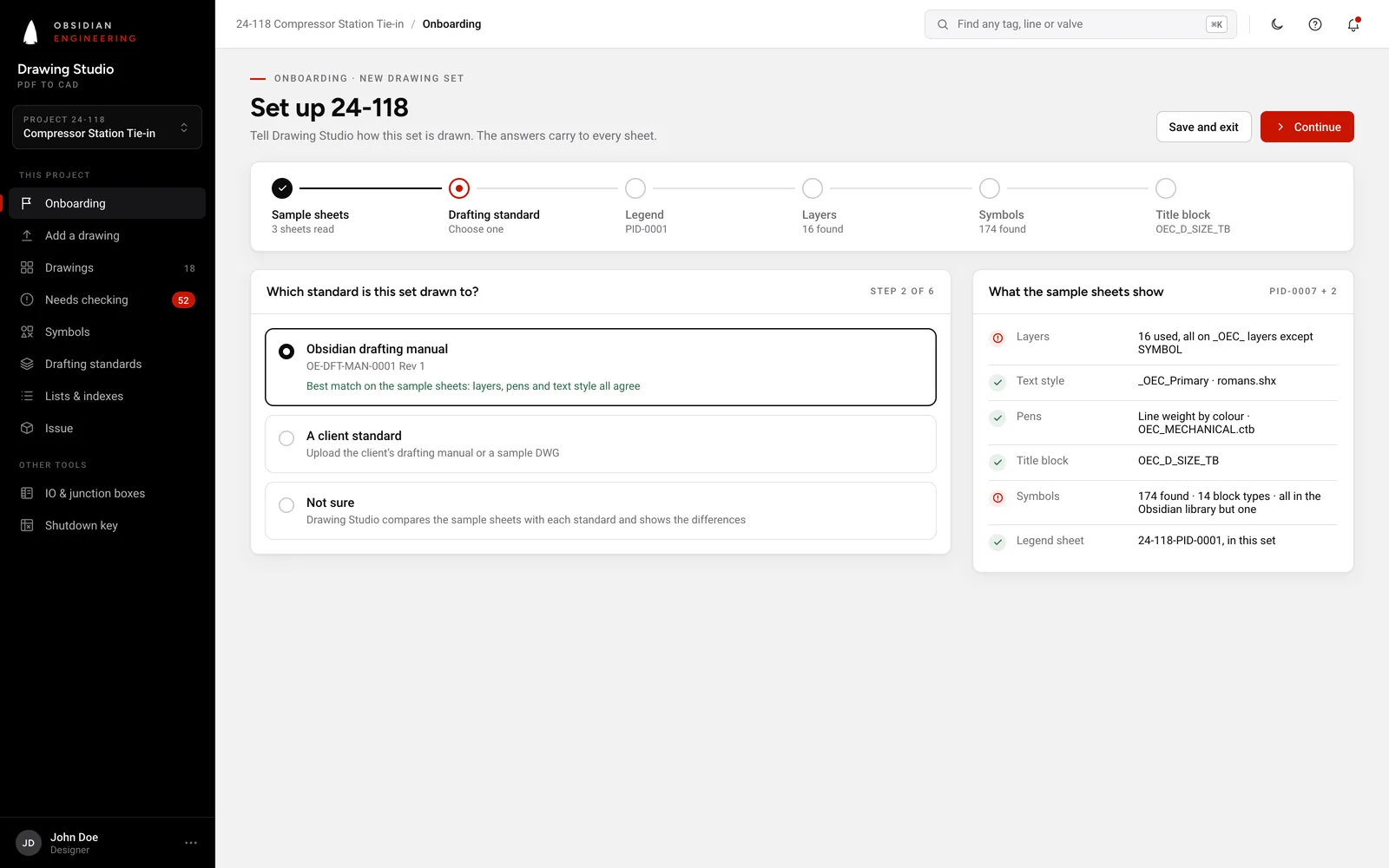
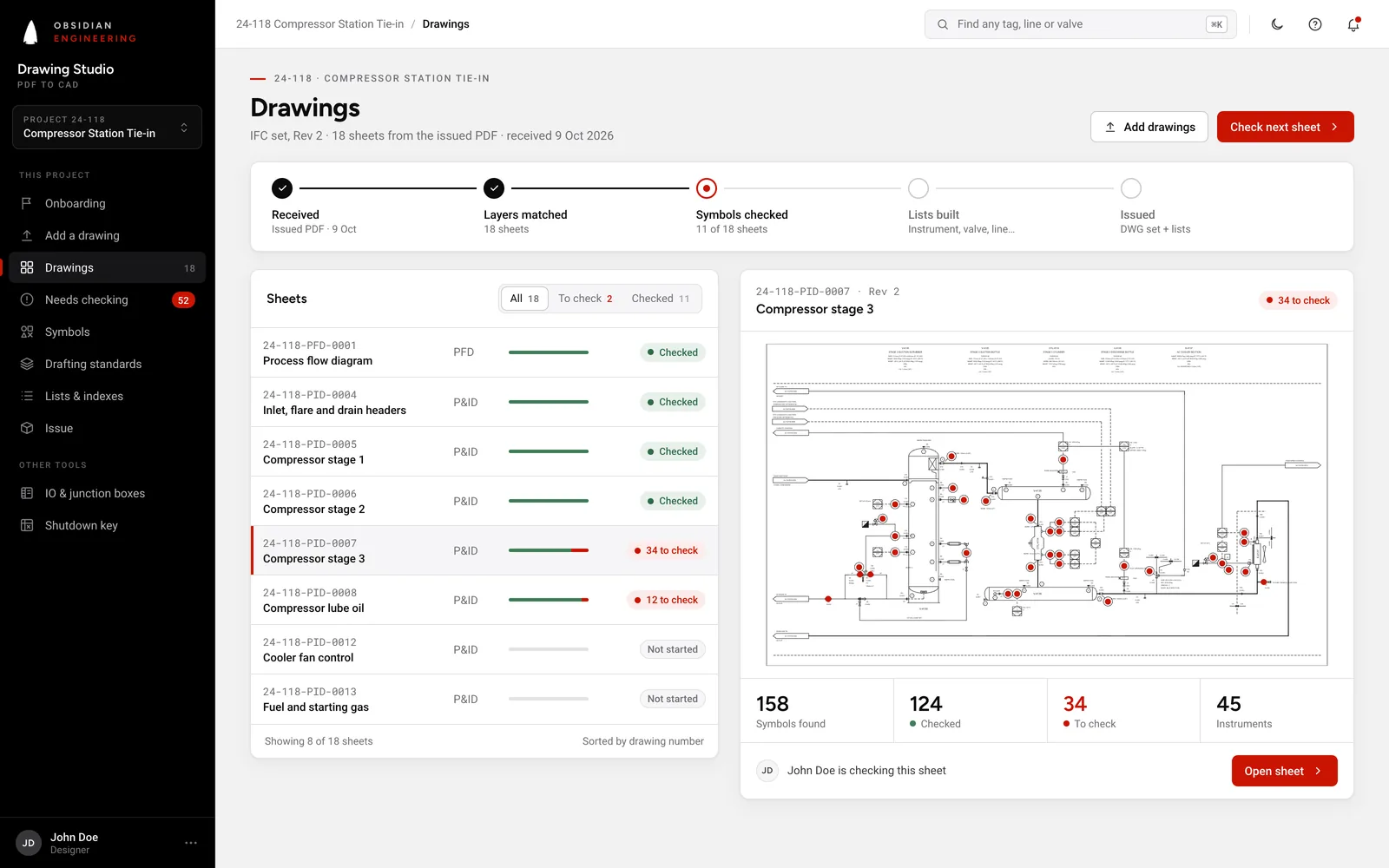
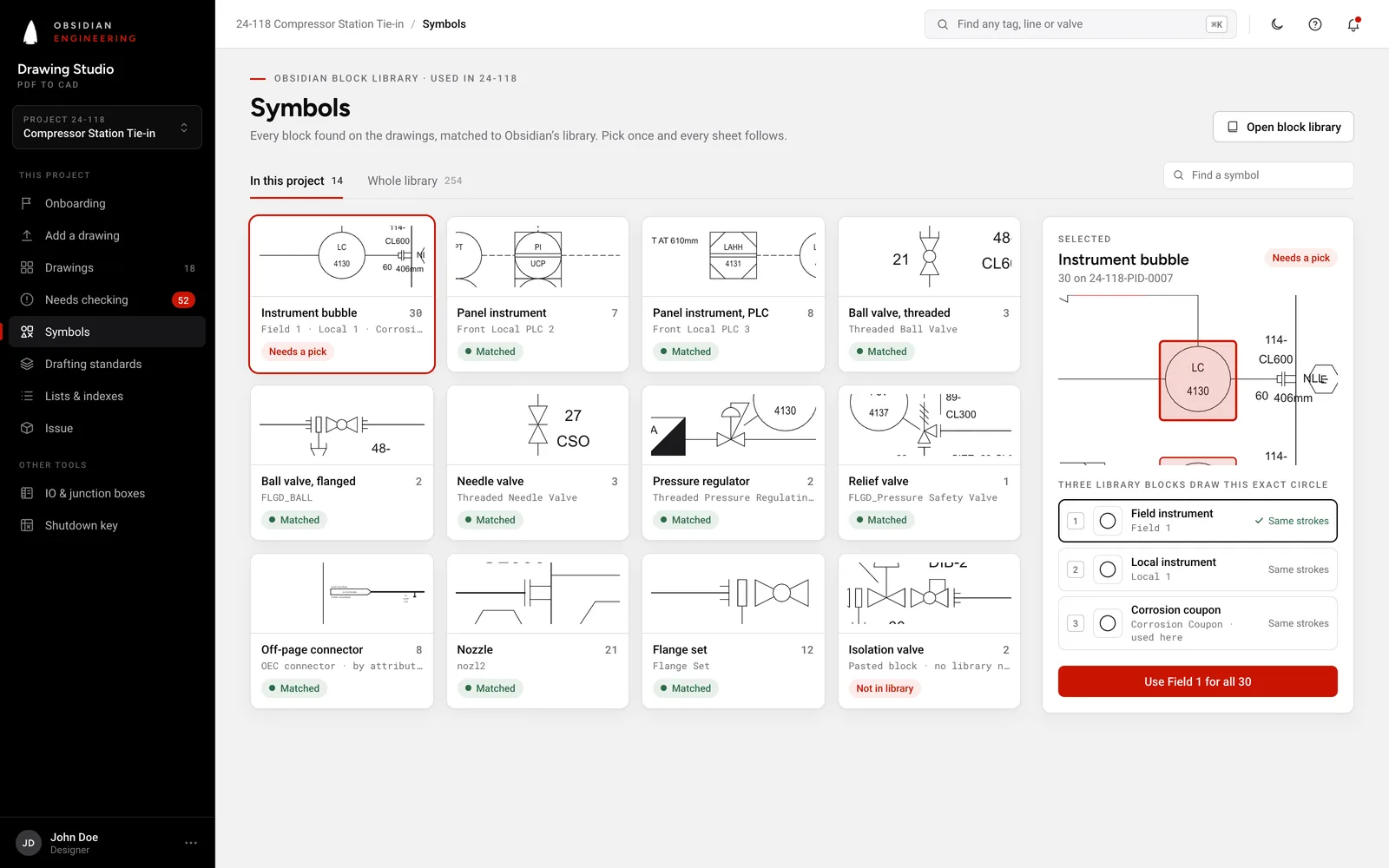
The tool being built for Obsidian's drafters, on the same drawing. Nothing is issued until a drafter has checked it.
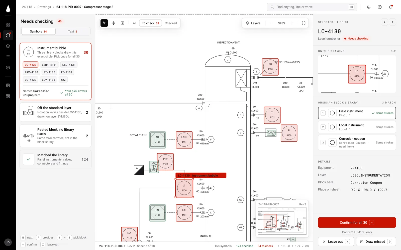
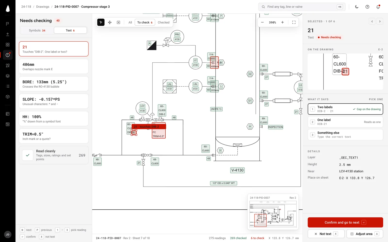
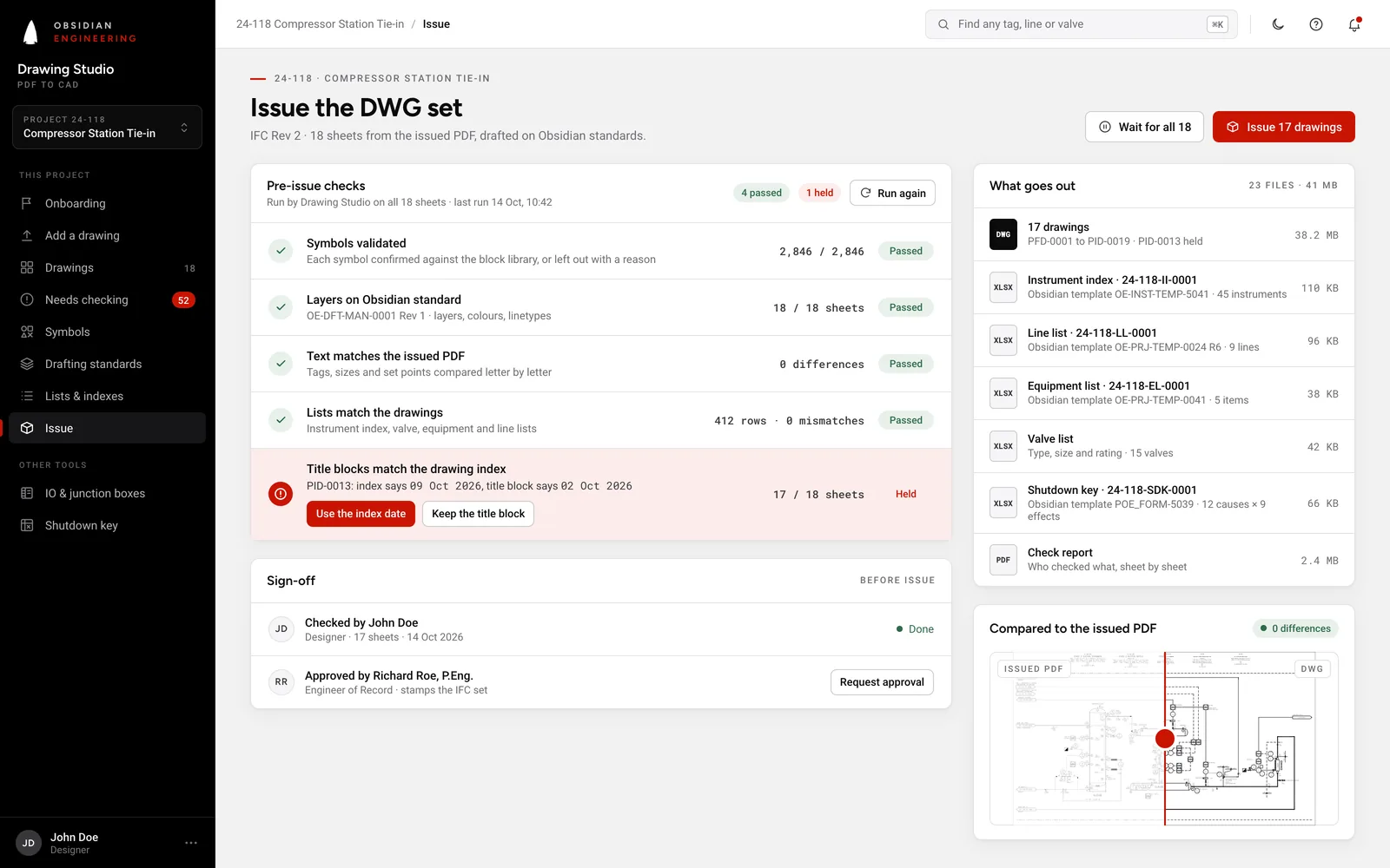
2 CAD to lists Demonstrated
Each line traced end to end, then every piece of equipment, valve, instrument, car seal and off-page connection, found where it sits on the layered drawing.
85 items from one sheet, none of them retyped.
The lists Demonstrated
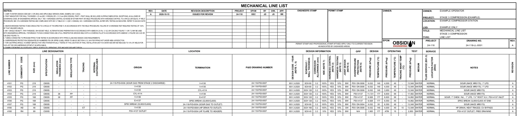
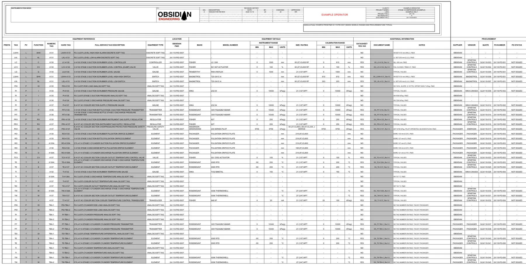
Read straight from the layered drawing, not retyped. Each row points back to its place on the sheet.
| Item | Type | Size |
|---|---|---|
| V01 | Diaphragm valve | 60-CL600 |
| V02 | Flanged ball valve | 48-CL600 |
| V04 | Flanged pressure safety valve | 60-CL900 x 89-CL300 |
| V08 | Threaded ball valve | 60-CL600 |
| V10 | Threaded gate valve | 60-CL600 |
+ 10 more rows
| Size | Class | From | To |
|---|---|---|---|
| 8" | CL600 | 24-118-PID-0006 | V-4130 |
| 8" | CL600 | V-4130 | V-4135 |
| 8" | CL900 | V-4135 | CYL-4114 |
| 8" | CL900 | CYL-4114 | V-4136 |
| 6" | CL900 | V-4136 | E-4137 |
+ 3 more rows
| Tag | Equipment |
|---|---|
| CYL-4114 | Stage 3 cylinder |
| E-4137 | AC cooler section |
| V-4130 | Stage 3 suction scrubber |
| V-4135 | Stage 3 suction bottle |
| V-4136 | Stage 3 discharge bottle |
| Tag | Function | Mounted |
|---|---|---|
| LAHH-4131 | Level alarm, high-high | Panel (PLC) |
| LAL-4131 | Level alarm, low | Panel (PLC) |
| LC-4130 | Level controller | Field |
| LCV-4130 | Level control valve | Field |
| LG-4130 | Level gauge | Field |
+ 40 more rows
The same rows go into Obsidian's own line list, instrument index, equipment list and shutdown key templates. What the drawing says is filled from the drawing; what a P&ID doesn't show is marked typical.
3 Electrical I/O and junction boxes In use
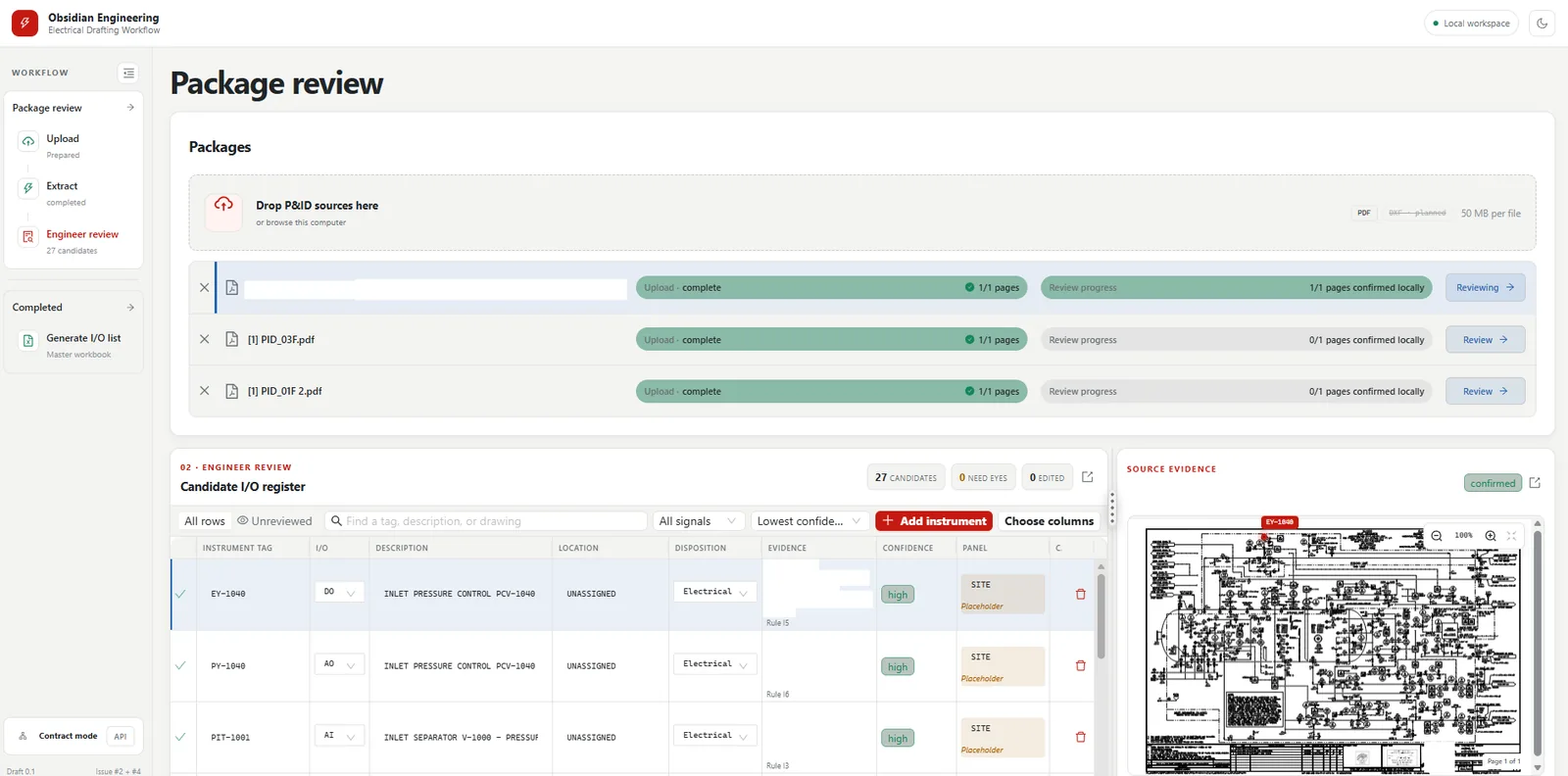
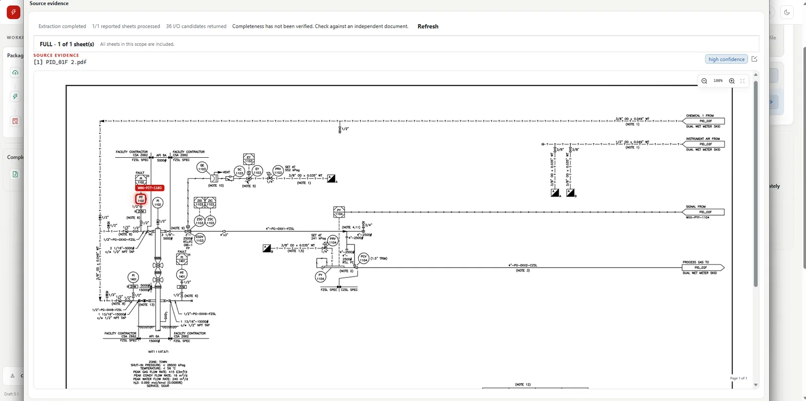
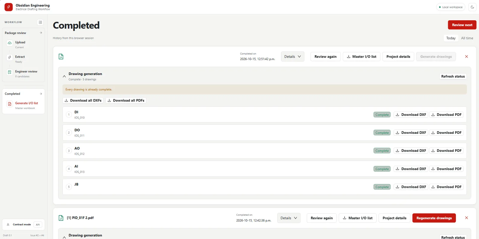
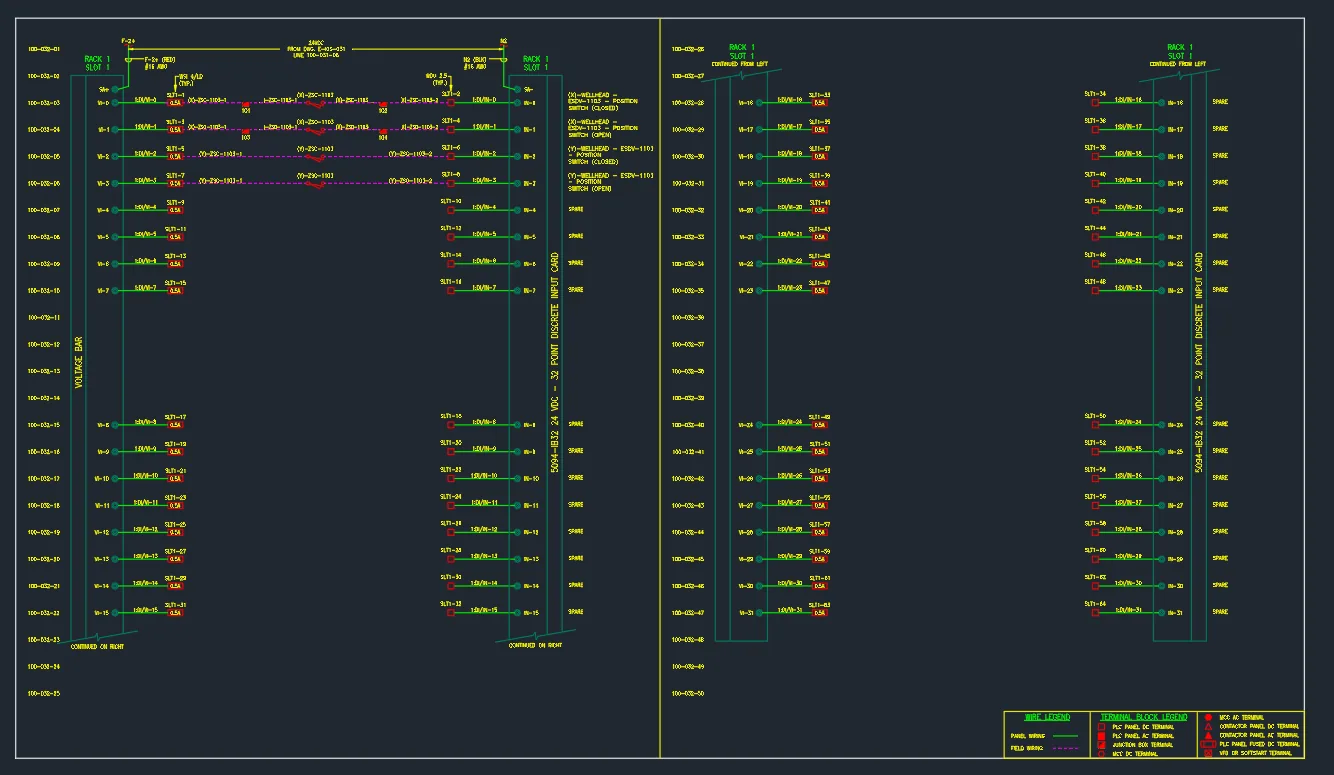
The tool reads the P&ID and lists every electrical instrument with its signal type. An engineer confirms each row against the drawing, then one step draws the I/O and junction box drawings as DWG and PDF.
4 Shutdown key In development
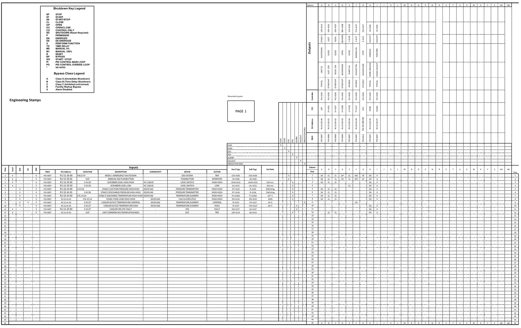
Every trip on the drawing, with its tag and set point, in Obsidian's shutdown key template. What each trip closes or stops is typical here: a P&ID doesn't show it.
PLC logic Future direction
One rung per trip, written from the shutdown key: the level switch, the pressure trip, the valves it closes, the cooler loop. Illustrative, with example tags; no real program is shown.
Program check In development
Every cause and what it does, rebuilt from the logic alone and compared with the key: 11 of 12 match, and one set point doesn't. Illustrative: we changed that set point on purpose to show the check catching it.
| Cause, read from the program | Tag | Set point | UCP-4114 | SDV-4101 | SDV-4107 | BDV-4108 | LCV-4130 | TCV-4137 | EM-4137 | XA-4100 | XC-4100 | Against the key |
|---|---|---|---|---|---|---|---|---|---|---|---|---|
| Mode 1 emergency shutdown | ESD-4100 | — | SD | CL | CL | OP | CL | M0 | SP | EN | X | ✓ |
| Manual ESD pushbutton | HS-4100 | — | SD | CL | CL | OP | CL | M0 | SP | EN | X | ✓ |
| Scrubber level high-high | LSHH-4131 | 610 mm | SD | CL | CL | EN | X | ✓ | ||||
| Scrubber level low | LSL-4131 | 203 mm | CL | EN | X | ✓ | ||||||
| Stage 3 suction pressure high-high | PIT-4135 | 4590 kPag | SD | CL | CL | EN | X | ✓ | ||||
| Stage 3 discharge pressure high-high | PIT-4136 | 7200 kPag | SD | CL | CL | EN | X | Set point: program 7200 kPag, drawing 7260 kPag | ||||
| Stage 3 discharge temperature high-high | TE-4136A | 107 °C | SD | CL | CL | EN | X | ✓ | ||||
| Stage 3 rod load high-high | PDI-4135 | 100 % | SD | CL | CL | EN | X | ✓ | ||||
| Cooler outlet temperature control | TE-4137 | 49 °C | CO | ✓ | ||||||||
| Cooler outlet temperature high | TE-4137 | 60 °C | EN | X | ✓ | |||||||
| Cooler fan VFD fault | EM-4137 | — | EN | X | ✓ | |||||||
| Unit common shutdown (package) | UCP-4114 | — | CL | CL | EN | X | ✓ |
5 What's next
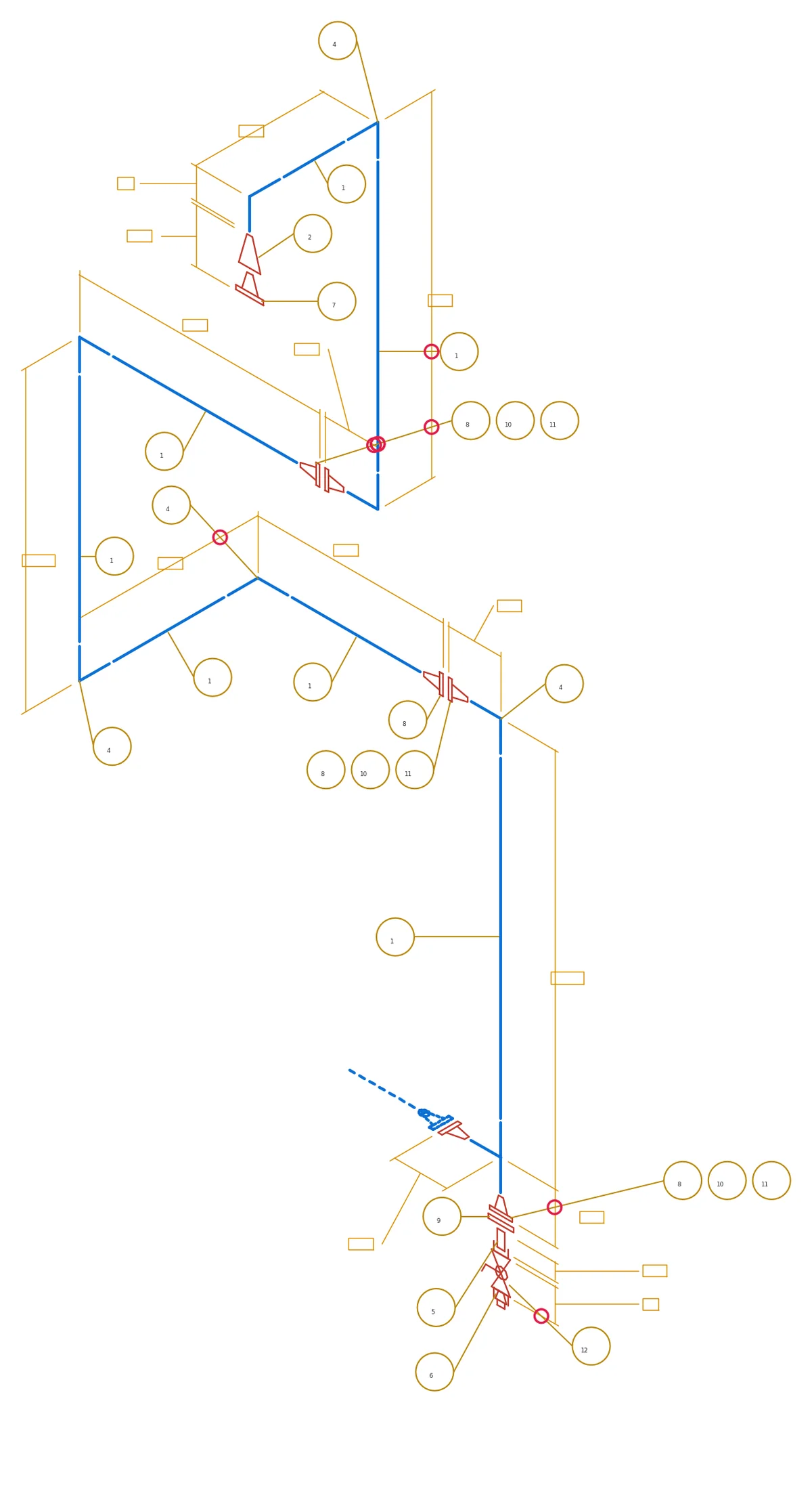
A workflow that lays the bubbles out and addresses collisions. Demonstrated
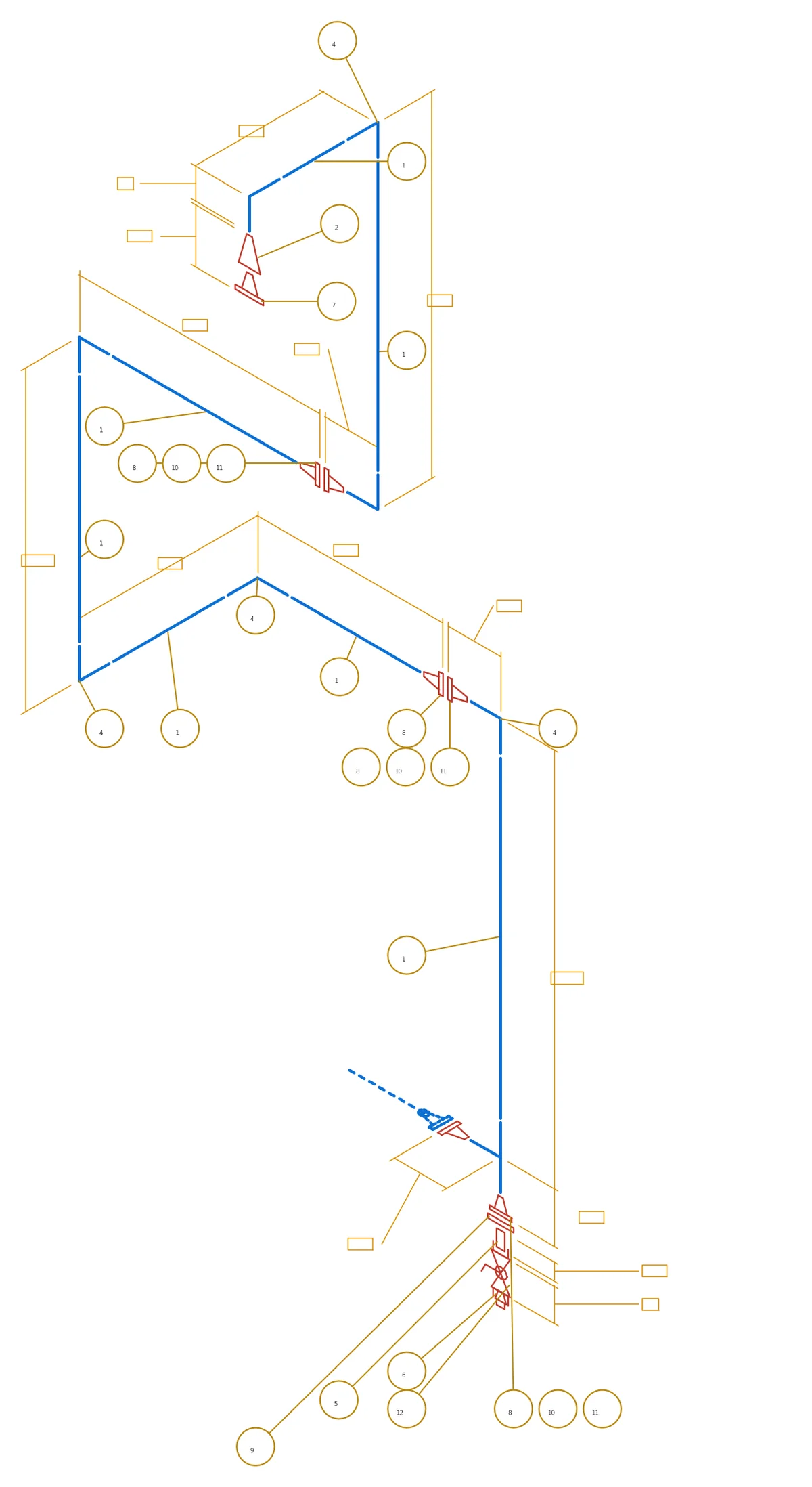
Capabilities as of October 2026. The drawing stays the anchor; engineers keep the design decisions, and every result can be checked against its source.
Start small enough to check every result: one drawing family, and one workflow that matters. We map today's workflow with your team first, so the result is measured against it.
One representative drawing family, its conventions, and the deliverables made from it today.
Recover layers, objects, tags and connections. Measure coverage against the source; send anything uncertain to review.
Editable CAD, a list, a reconciliation, or one engineering rule set, measured against how it's done today.
Talk to us about a pilot info@obsidianeng.ca